A complete guide to installing, wiring, and calibrating the Dwyer GSTA-C CO gas sensor. Covers common installation mistakes, safety rules, troubleshooting, and maintenance to ensure accurate CO monitoring in HVAC systems and parking garages.
User Guide for the Dwyer GSTA-C CO Gas Sensor: Installation – Wiring – Calibration
The Dwyer GSTA-C CO gas sensor is a specialized transmitter designed for HVAC systems, parking garages, tunnels, and confined areas where carbon monoxide buildup may occur. Depending on the version, the device provides 4–20 mA / 0–10 V analog outputs or Modbus RTU, ensuring continuous monitoring and seamless integration with BMS, PLCs, or ventilation control systems.
This guide helps you install, wire, operate, and troubleshoot the GSTA-C correctly based on technical standards to ensure accuracy, durability, and long-term stability.
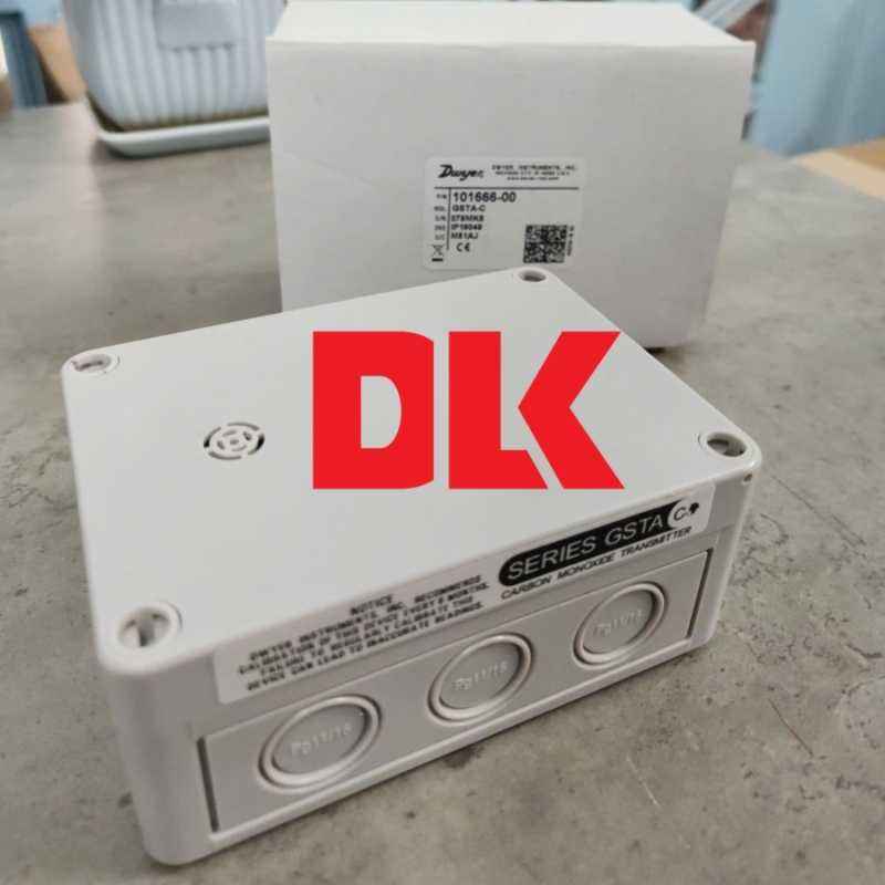
Dwyer GSTA-C CO Gas Sensor
1. Common Installation Mistakes with the GSTA-C Sensor
In real-world projects, improper installation is the leading cause of inaccurate readings or premature sensor failure. Below are the most common mistakes:
1.1. Mounting the sensor at the wrong height
Carbon monoxide has a density close to air and typically distributes evenly. A common mistake is installing the sensor too close to the ceiling or floor.
Correct mounting height: 1.2–1.5 meters above the ground.
1.2. Installing the sensor near heat sources
Heat sources such as vehicle exhaust pipes, heaters, CPU cabinets, or hot walls can distort the sensor’s temperature environment and affect measurement accuracy.
1.3. Incorrect output wiring
The GSTA-C supports multiple output types:
• 4–20 mA (loop-powered or 3-wire)
• 0–10 V
• Modbus RTU (select versions)
Miswiring can cause loss of signal or incorrect readings.
1.4. Lack of periodic calibration
Electrochemical CO sensors require verification or calibration every 6–12 months, depending on building safety requirements.
2. Safety Rules Before Installation
To protect both the technician and the system, follow these essential safety practices:
2.1. Disconnect all power before wiring
Never work on the unit while the system is supplying 24 VDC/24 VAC.
2.2. Avoid drops or physical shock
The electrochemical cell is sensitive to mechanical impact and may be damaged by strong shocks.
2.3. Do not open the enclosure in hazardous atmospheres
Opening the housing in high CO concentration areas may affect the sensor and pose danger to the operator.
2.4. Use proper cable types
• Twisted-pair cable for Modbus RTU
• Shielded cable for long-distance runs
• Minimum conductor size: 0.5 mm²
3. Step-by-Step Installation Guide
Step 1: Select the installation location
Choose a position that:
• Is 1.2–1.5 m above floor level
• Is away from heat sources
• Is not directly in front of strong airflow
• Allows easy maintenance and inspection
Step 2: Drill and mount the base plate
Use two expansion screws to secure the sensor base to the wall. Ensure the mounting surface is flat and dry.
Step 3: Route the power and signal cables
The GSTA-C features a twist-lock cover with dust seal. Ensure cables are properly routed and not pinched.
Step 4: Wire the sensor according to the correct diagram
4.1. For 4–20 mA (loop-powered)
• Terminal 24V: 24 VDC supply
• Terminal OUT: return to analog receiver
• Terminal GND: common ground for power and signal
4.2. For 0–10 V output
• 24V – power supply
• OUT – 0–10 V signal
• GND – common
4.3. For Modbus RTU (if equipped)
• 24V – power supply
• A(+) – RS485+
• B(–) – RS485–
• GND – common
Step 5: Close the cover, power up, and check status LED
Upon powering:
• LED indicates stable power supply
• Allow 30–60 seconds for the sensor to stabilize before reading values
4. Calibration Procedure for the GSTA-C CO Sensor
The GSTA-C uses an electrochemical CO cell, making routine calibration essential. The standard calibration process includes:
4.1. Zero Calibration
• Use clean air (0 ppm CO) or fully ventilate the area
• Wait 3–5 minutes for stable readings
• Press the Zero button on the board (depending on version) or perform via Modbus command
4.2. Span Calibration
• Use a calibration gas cylinder: 50 ppm or 100 ppm CO
• Apply gas to the sensor chamber for ~2 minutes
• Adjust the trim pot or Modbus parameter to match the target reading
Note: Do not perform calibration when temperature fluctuates heavily or when exposed to strong airflow.
5. Troubleshooting Common Problems
5.1. No output signal
Possible causes:
• Incorrect power wiring
• Insufficient 24 VDC/24 VAC supply
• Output terminal shorted
Solution: measure Vout — if <1 V or <4 mA, the sensor may be faulty.
5.2. Unstable or fluctuating readings
Causes:
• Unshielded signal cable
• Cable routed parallel to 220 V power lines
• Ground not connected properly
5.3. Output stuck at high level
Causes:
• CO cell degradation
• Constant exposure to high CO levels
• ADC circuit malfunction
5.4. Modbus communication failure
Check the following:
• Baudrate (typically 9600)
• Parity settings (N, 8, 1)
• Slave ID (factory default is usually 1)
6. When to Replace or Maintain the GSTA-C Sensor
• Replace the CO electrochemical cell every 24–36 months
• Replace if readings deviate >10% even after calibration
• Replace after exposure to extremely high CO concentrations
• Inspect if installed in damp, corrosive, or condensation-prone environments
7. Applications and Related Resources
For additional specifications, configuration details, or quotations, refer to:
➡️ GSTA-C – High-accuracy outdoor CO sensor
➡️ GSTA-C: CO gas sensor with Modbus RTU communication
Conclusion
The Dwyer GSTA-C is a durable and technically reliable option for CO monitoring in parking structures, basements, and other confined spaces. Proper installation, wiring, and routine calibration ensure accurate measurements and long-term sensor performance.
For further assistance with model selection, HVAC engineering integration, or technical documentation, you may contact DLK Trading Service Company Limited., the official distributor of measurement instruments from Dwyer, Omega, Honeywell, and other leading manufacturers.